This article mainly discusses the application of active liquid cooling measures to the use of LED lights in automotive headlamps. After the air cooling and passive liquid cooling methods were tried, they were excluded because they did not meet the standard, so the active liquid cooling method was adopted. In this paper, several active liquid cooling systems are analyzed and the optimal solution for heat management is found through research on optimization.
1 Introduction
Compared with incandescent light sources, LEDs have a small package size, various forms, and excellent performance. Recently, they are widely used in automotive exterior lights. For example, white LEDs are used in automotive headlights. Although LED lights have more and more development prospects in automotive headlights due to their excellent performance, it is still in the initial stage to achieve the level of white LEDs that can be used in automotive headlights. At present, the application of LED in automobile headlights is only in some concept cars, and it has not been popularized in the field of civilian cars.
At present, the application of LED lamps in the field of vehicles has problems that need to be solved, such as insufficient luminosity and high cost. The regulations stipulate that the brightness of vehicle headlights requires each lamp to reach 750lm, and the current average output of high-brightness LEDs is only 40lm / W, so a larger number of LEDs and higher power supply are required to meet the above standards.
With the increasing requirements for luminous flux output, the power supply of LEDs will continue to increase. The heat management of LED packaging needs more and more attention in vehicle applications, because its heat dissipation will seriously affect the efficiency, performance and reliability of LEDs.
If the diode junction temperature is too high, it will reduce the LED efficiency and the emission wavelength will shift. Therefore, the LED operating temperature must be below its maximum allowable operating temperature (125 ℃), in order to make its best efficiency and light color deviation is not large. Therefore, the use of heat dissipation measures must be omnidirectional and full-scale—from single device, package level, board level to system level thermal analysis. Die-emitting LEDs have been used for commercial thermal analysis applications. Thermal analysis simulation uses CFD (Computational Fluid Dynamics) method to carry out all-round thermal analysis of each stage of such LED and then find out a more appropriate heat dissipation scheme. This paper uses CFD software FloTHERM to study the design of heat dissipation optimization measures.
2. Selection of active liquid cooling method
2.1 From device to board level
Take the Cree XBright900 type LED as an example. This LED is a 900 * 900 micron chip provided as a commercial die. This LED produces a wavelength of 460-470nm in a 2.5nm space and the color is blue. It is necessary to control the heat dissipation of the 2.7W heat emitted by each LED. This LED system is composed of 15 small LEDs distributed on 5 circuit boards every 3 LEDs.
To simplify the installation process, each LED is individually packaged. In turn, the LED needs to use a layer of phosphorescence to make the GaN (gallium nitride) -based LED convert blue light into white light (visible light) and emit it. The generated heat is dissipated directly to the package housing through the device. Therefore, ceramic sheets with high thermal conductivity need to be selected to provide a smaller thermal resistance path and better electrical insulation. AIN ceramic material (K = 200W / mK) is very suitable as a good conductor for heat dissipation under high power. The calculated thermal resistance between the LED and the bottom of the AIN ceramic package is less than 2 ° C / W.
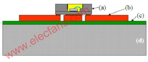
Figure 1 Insulated metal basic component (IMS) (a) The AIN material package is connected to the LED with a gold wire,
(b) Circuit layer, (c) Dielectric layer, (d) Aluminum substrate
The AIN ceramic package is mounted on an insulated metal substrate (IMS) (Figure 1). The IMS substrate provides thermal diffusion and heat sink to provide a good thermal path to greatly simplify the design of this system. IMS consists of three layers: copper foil circuit layer, thin dielectric layer and aluminum substrate.
Several materials composed of the dielectric layer and the three-layer structure of IMS with different thicknesses are compared in thermal analysis. It is found that the optimal board should be a thicker circuit layer to transfer heat at a faster rate plus a thin layer and thermal conductivity Very high dielectric layers to reduce their thermal resistance, the thickness of these layers is determined by the IMS manufacturing process. The specific IMS structure selected in this article is shown in the following table: 70μm copper layer, 75μm dielectric layer thermal conductivity 2.2W / mK and 1mm thick aluminum substrate.
Table 1. Materials in IMS board structure and model
2.2 System level-air cooling
Application of car headlights requires that the light must be forward. For this purpose, the IMS board needs to be placed on the 45-degree surface behind the headlamp assembly. For passive cooling, the heat sink is installed directly on the back of the IMS board. In practice, the entire system should be placed in the cavity of the headlamp to exchange heat through convection. Due to the limited cavity size, the size of the heat sink is limited. As shown in Figure 2, the junction temperature of the LED far exceeds its maximum allowable value of 125 ℃.
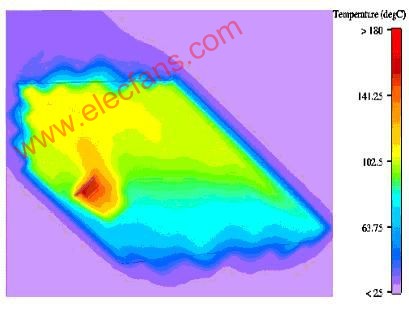
Figure 2. Passive cooling scheme headlight profile temperature cloud (Tj = 200 ℃)
Active air cooling has also been studied. However, it is not feasible to use a larger number of high-speed fans due to the inherent space and constraints of the surrounding parts. From its reliability, cost and processing considerations are not feasible. In summary, liquid cooling measures have been identified as the next research direction.
2.3 System level-passive liquid cooling
There are two types of passive liquid cooling that can be considered: passive closed loop and heat pipe.
The simulation results show that the passive closed cycle can meet the requirements, and the junction temperature of the LED can be maintained at the maximum allowable operating temperature. However, the liquid driving force in passive systems is obtained through buoyancy. Therefore, this system requires a heat exchanger to be placed on the heat source, and the hotter, lighter liquid (such as water) formed in it will go up and be cooled against gravity. Although it is feasible from a thermal point of view, in practice this method is not suitable for cooling the headlamp, because the design of the headlamp requires that the heat exchanger must be placed under the LED lamp.
For the heat pipe cooling method, a circulating heat pipe system is just a heat cycle in the system. However, each LED board needs to be separately equipped with a heat pipe system, which greatly increases the cost of the entire LED lamp cooling system. The price of flexible heat pipe products (such as Thermotek, Dau) is about 1000 $ each. Moreover, even if it is feasible from the perspective of heat dissipation analysis, it is not feasible to use heat pipe cooling because of its engineering difficulty and cost.
In summary, the cooling measures required to address the application of high-brightness LEDs in the automotive industry need to be directed to active cooling methods.
3. Active cooling
3.1 System structure
The liquid cooling system includes the following: pump, cold plate connected to the heat source (IMS plate), reservoir and heat exchanger. They are connected by pipes to form a closed loop system.
Since each board needs to be adjusted, each cold plate needs to be attached to each corresponding board separately. Due to weight and volume limitations, and the high beam and low beam will not be turned on at the same time, the high beam and low beam use a heat exchanger together. In turn, more heat can be taken away with a double volume heat exchanger. The heat exchanger is composed of a heat sink and a liquid cooling coil at the bottom. Considering the thermal characteristics and ease of use, the working fluid used in the cooling system is mainly water with additives (additives such as antifreeze, ethylene glycol, anti-algae and antibacterial agents, etc.)
There are several combinations to consider. In order to reduce damage to the pump and improve its reliability, the liquid-cooled part of the pump is visible. The first option is to place five low beam and high beam (LB-HB) circulation systems in parallel (Figure 3). From the perspective of ideal thermal analysis, two sets of manifolds plus two water delivery hoses and connecting parts are required. However, this solution makes the entire system too complicated, so it is not suitable for adoption.
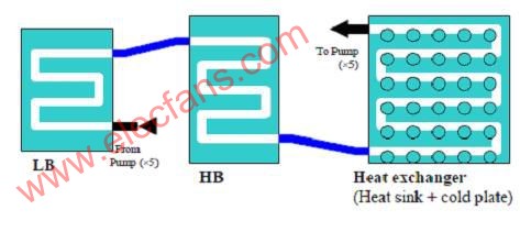
Figure 3 Cold plate and radiator design and hose connection
The second solution consists of the same 5 LB-HB cold plate circuits, but the link between them is formed by a single cycle. This long circulation path results in a large pressure drop. Thermal analysis simulation results show that the pressure drop of the loop is just below the pump head, so it will not cause adverse effects on the cooling system in terms of heat dissipation.
Finally, an alternative solution is introduced. This liquid solution is a loop through a series of low beam (LB) cold plates, then through a series of high beam (HB) cold plates, and finally through the radiator (Figure 4). The advantage of this design is that the number of tubes is reduced from 17 to 14. The smaller number of tubes is advantageous for the two lights to be adjusted separately and easy to install. Thermal analysis shows that the junction temperature of the three LEDs on the last board in the entire circuit in this scheme is only 5 degrees higher than the corresponding junction temperature in the first scheme.
Figure 4 Active liquid cooling device structure: the liquid cooling circuit connects all the LB cold plates and then flows into the HB plate and then into the radiator
Figure 5 is a three-dimensional simulation model established by FloTHERM analysis.
Figure 5 Full active liquid cooling model of a complete low beam light system in the headlamp space
3.2 Thermal optimization
3.2.1 Liquid flow optimization
Figure 6 shows the variation curve of the LED temperature calculated under the nominal flow rate of the pump (pressure drop is 0). As the nominal flow of the pump increases, the LED junction temperature gradually decreases. However, when the flow rate is higher than 0.12 l / s, the junction temperature does not change significantly.
Figure 6 Calculated LED junction temperature curve (blue line) and IMS board temperature (red)
Figure 7 shows the relationship between nominal flow and actual flow. For a lower nominal flow rate, the pressure drop of the fluid changes very little. However, as the flow rate increases, the pressure drop of the liquid circuit limits the actual flow rate. The relationship between pressure drop and flow in the circuit shown in Figure 8 and the linear characteristics of the pump are at a nominal flow rate of 0.12 l / s and a nominal pressure head (when no flow) of 25 kPa. The results show that the closed pump needs to be operated within a suitable working point range to be more reasonable.
Figure 7 Comparison curve of nominal flow and actual flow of pump
Figure 8 Pressure and flow characteristic curves composed of the linear characteristics of the liquid-cooled circuit and the pump
3.2.2 Optimization of heat exchanger (heat sink)
The design of the heat sink depends on its external conditions, such as the type of air flow and working environment, which all determine the placement of the device and the air flow rate. In this example, the heat sink is placed horizontally, because the direction of flow cannot be selected, so in order to reduce the overall weight, the shape of the teeth of the radiator needs to be selected.
There are many parameters that need to be considered for the optimization of the shape of the radiator, such as the length of the teeth, the number, and the thickness of the base. Since the above parameters will affect the LED temperature, iterative procedures are required to evaluate a series of parameters. The following is the conclusion of the study on the series of parameters:
1) Heat sink base thickness (t). Based on its connection under the cold plate and then transferring heat to the entire area, the thickness of the base has little effect on the LED temperature. In order to reduce the weight of the heat sink, the thickness should be reduced as much as mechanically possible. Make sure to choose a thickness of 5mm.
2) Heat sink height (H). The overall height of the heat sink is equal to the base thickness (t) plus the tooth height (h). The tooth height is the most important parameter in this optimization. Try to use a higher size, but be careful not to block the light.
3) Length of tooth plate (l). The calculated optimal value is 4.5mm. However, the sensitivity of the LED temperature to fluctuations in the tooth length around the optimal value is very small. According to the simulation situation, when the value changes between 3.5-6mm, the temperature fluctuation is less than 1 degree. Therefore, the length of the tooth plate is acceptable within the above range.
4) Width of tooth plate (w). The calculated optimal value is 9mm. Similar to the tooth length, when the tooth width changes between 7.5-10mm, the temperature fluctuation is very small.
5) Number of teeth in the X direction (Nx). Calculate 40 optimal values, and the tooth spacing in this direction is 5.1mm. From the thermal simulation results, the number of teeth in the X direction in this example is changed between 35-45.
6) Number of teeth in the Y direction (Ny). Due to the limitation of the headlight space, put as many teeth as possible on the widest side and a smaller number on the narrowest side. After calculation, the optimal value is 7 and the distance is 4mm. More than 7 are also feasible.
7) The final optimized heat sink weight of the aluminum radiator is less than 800 grams.
Figure 9 Heat sink parameters and three-dimensional dimensions
Because this series of optimization parameters will affect each other (such as tooth length and tooth width), these factors need to be considered simultaneously during the entire optimization process. (See Figure 10)
Figure 10 LED temperature changes when the tooth length and tooth width change each other A) 3D view B) Sectional view
Other parameters (such as the number of teeth) are independent parameters and can be optimized independently (see Figure 11).
Figure 11 Relationship between LED temperature and number of teeth (X direction: dark blue; Y direction: pink)
In short, the optimized heat sink size is as follows (unit: mm)
Optimization Results
t = 5, H> 30, h> 25, l = "4" .5, w = 9, Nx = 8, Ny = 7
Fine-tunable parameters (junction temperature change less than 1 degree)
3.5
4 Conclusion
This article describes the active liquid cooling method and its optimization for the application of high-brightness LED lights in innovative automotive headlights.
The article explains that the methods of air cooling and passive liquid cooling either cannot meet the maximum allowable temperature of the LED junction temperature or cannot be realized in practice. Although some methods are feasible from the perspective of heat dissipation analysis, considering the optical and mechanical aspects, they cannot meet the requirements. Therefore, in order to find a suitable thermal management method, it is necessary to fully consider the design of the headlamp.
Based on this active liquid cooling method was determined as the most suitable optimization scheme. This article describes several different active liquid cooling schemes and conducts comparative studies. Heat dissipation optimization also includes liquid flow optimization and heat sink optimization to maximize its heat dissipation performance. In the optimization of the entire optimization plan, the thermal aspect is not the only factor considered. All relevant aspects have been considered, such as process manufacturing and product specific requirements.
With the development of high-brightness white LEDs, the power supply for specific light will continue to decrease in the future. Therefore, the amount of heat dissipation is also reduced. As the power to the system is reduced and the amount of heat dissipation is reduced, the cooling method may again use passive cooling.
MAINTEX Car Parking automatic gate barrier & boom barrier gate: 0.5s to 4s Lifting or Falling Speed, APP Set All Parameters, 30V Low-voltage Brushless dc motor, Long Life & Strong Anti-interference.
If you want barrier gate , boom barrier , boom gate , gate barrier , automatic gate barrier, barrier gate price, car parking gate , Boom Barrier gate or Other Products , please contact us to Customize for you.
Boom Barrier
barrier gate,boom barrier,boom gate,gate barrier,automatic gate barrier,barrier gate price,car parking gate,boom barrier gate
Shenzhen Maintex Intelligent Control Co., Ltd. , https://www.maintexmotor.com