Cognitive radio CR (CogniTIve Radio), as a new type of spectrum sharing technology, realizes the intelligent spectrum and opportunistic use of spectrum holes in licensed frequency bands (that is, free spectrum that has been allocated to authorized users but not occupied by them) Reuse of non-renewable spectrum resources. In order to effectively solve the contradiction between the shortage of spectrum resources and the low spectrum utilization rate in today's wireless networks, a new approach has been opened.
This article proposes a concept based on cognitive radio, which combines the MSP430F2418 microcontroller with the nRF905 radio frequency transmission module, through carrier detection and algorithm control, to realize the intelligent access design scheme of unauthorized users in wireless networks, focusing on how to use The concept of cognitive radio was put into practice.
1 The establishment of the hardware platform Figure 1 shows the communication architecture of the cognitive network. In the figure, UCR represents an authorized user, F1 is its authorized frequency; CR represents an unauthorized user, CR_Tx is the sender of the unauthorized user, and the intelligent access function of the unauthorized user in the network is completed by it; CR_Rx is the reception of the unauthorized user Party, whose main task is to accurately receive data from the sender. In the figure, Fn is a variable frequency. When UCR does not use F1, CR users can use F1; otherwise, CR users should avoid this frequency. Since the frequency of this study is the 433.0 MHz license-free application band, the nRF905 RF transmission module that can work at 433/868/915 MHz was selected. In order to visualize the working performance of unauthorized users, a liquid crystal display is added to the hardware, which combines with the buttons to form a human-computer interaction interface. The function of intelligent access for unauthorized users requires a microprocessor for processing and control. The MSP430F2418 single-chip microcomputer with ultra-low power consumption and large memory was selected in the subject. The huge memory space of this type of single chip microcomputer provides convenience for future system function expansion and meets the design needs.
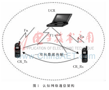
Figure 2 shows the hardware connection diagram of MSP430F2418, nRF905, and LCD, omitting the key part. CPU mainly operates the internal registers of nRF905 through P2 and P3 ports to make it work in different working states. Both cognitive senders and receivers need to perform spectrum detection on the currently set frequency band to determine spectrum holes and select the best carrier frequency, all of which are based on the detection of the signal on the CD pin of the nRF905 module by MSP430F2418 . For the liquid crystal display, the CPU is mainly controlled by the lower four bits of P5 port and P4 port. In addition, the buttons omitted in the figure and the liquid crystal display combine to form a human-computer interaction interface, and the network can be set to work in different frequency bands.

2 Communication protocol design
2.1 Custom data communication protocol Due to the dynamic, flexible, and intelligent characteristics of cognitive radio technology, the requirements for communication protocols are relatively high. The required protocol can adapt to the available spectrum resources due to terminal changes and wireless environment changes. Dynamic changes and changes in network topology. In particular, normal communication of unauthorized users cannot be interrupted due to changes in available spectrum resources. To this end, it is necessary to improve the existing communication protocol, and consider the cross-layer design of the physical layer and the data link layer. This article uses the most basic wait-and-wait protocol in the data communication protocol, that is, every frame of data sent must wait for the response frame before sending the next frame of data. In order to avoid the problem of redundant data frame retransmission in the waiting and waiting protocol, the sender codes a sequence number for each frame of data. The receiving party judges the data serial number to ensure that only the currently desired data frame is received.
In order to improve the accuracy of sending and receiving data, in addition to the CRC check code of nRF905, the design also marks the first character of the data block sent and received between unauthorized users as 'R'. The receiver only saves the data when the first character 'R' is correct. The data frame format is shown in Figure 3.

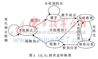
2.2 Data transmission and protocol analysis of the sender The sender of the unauthorized user has the perception capability, and the intelligent access function in the cognitive network is implemented by it. After the initialization is completed, the sender needs to perform spectrum detection on the currently set frequency band [3-5], separate the frequency points in the busy state and the idle state, and then find an optimal frequency among the idle frequency points point. After the best frequency is found, the sender then sends a handshake message. The sender will always be in a handshake state before receiving the response signal from the other party. After receiving the response signal from the other party, the sender enters the data transmission stage. In this stage, the sender must detect the currently used center frequency after sending a frame of data. If it is detected that the authorized user still does not use the frequency, the sender continues to send the remaining data until the data transmission is completed. If the sender detects that the current center frequency is being used by an authorized user, it should avoid this frequency point in time and re-find a new spectrum gap to establish a communication system. As shown in Figure 4.
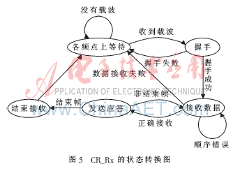
2.3 Data reception and protocol analysis of the receiver The basic task of the receiver is to receive data and save the received data. The state transition diagram is shown in Figure 5. Before waiting for the handshake signal from an unauthorized user, the receiver will perform cyclic scan detection at various frequency points. If a carrier is detected at a certain frequency, the receiver tries to shake hands. If the handshake fails, the receiver changes frequency and continues to detect. Once the handshake is successful, the receiver starts to receive data. In the data receiving stage, if the frequency of the sender remains unchanged, the receiver can complete the reception of all data without frequency conversion. However, if the sender switches the frequency during data transmission, the receiver has not received the data information on the original frequency, and needs to exit the data receiving state to re-execute the cycle scan detection, and continue to receive the remaining data after the successful handshake again . If it is found that the data sequence number is misaligned, in theory, the sender and receiver use the same frequency, you only need to adjust the pace. After testing, the receiver of the unauthorized user works steadily. When data misalignment occurs, the program can automatically adjust the pace according to a custom protocol to ensure that each frame of data is received correctly.
3 Software design
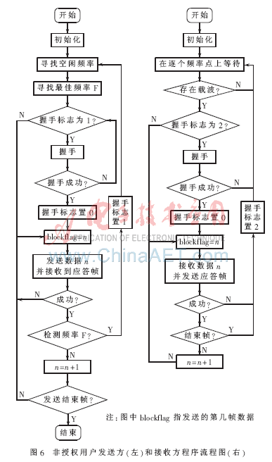
3.1 Program flow chart The system software design uses standard C language to write and debug in the IAR development environment. Fig. 6 is a flow chart of the procedure for the unauthorized user sender and receiver from frequency selection to sending data, omitting the liquid crystal display part.
3.2 The best frequency point selection algorithm Due to the different environmental conditions around each spectrum gap, in order to avoid interference with other user carriers as much as possible, unlicensed users need to find the best frequency point from several spectrum gaps.
The following program processes the idle frequency array and busy frequency array obtained by analysis. The algorithm pre-defines three arrays, which respectively store the frequencies where the frequencies on both sides are idle, the frequencies where the frequencies on the adjacent side are idle, and the frequencies where both sides are busy. The classification algorithm is as follows: add and subtract 5 × againflag in sequence to all the values ​​in the idle frequency array (the step distance between adjacent frequency control words is 5, and againflag is the number of repeated classification, the initial value is 1), The two values ​​of are matched with the data of the busy frequency array. According to the matching of the two values, the current frequency is allocated to the corresponding corresponding array defined in advance. The selection method of the return value is as follows: after classification, if there is only one frequency that is free on both sides, then return this frequency value directly; if it does not exist, return the frequency of one frequency idle; if it still does not exist, return Frequency where both adjacent frequencies are busy. If, after the first round of classification, there is more than one frequency that is free on both adjacent frequencies, a second round of classification is needed until the best frequency is found. In the special case where a certain frequency is idle, the program returns a value in the middle of this frequency.
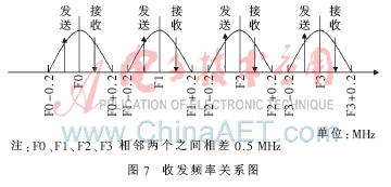
3.3 Transceiver frequency design Under normal circumstances, there are various obstacles around the transmitting antenna. If the sending and receiving frequencies are the same, then unauthorized users are likely to receive the reflected wave of the signal sent by them at the previous moment and cause the frequency switching. However, the frequency after switching is still the same as the frequency used last time, resulting in unstable system operation. Therefore, the design separates the sending carrier from the receiving carrier. After testing, the bandwidth of each carrier to transmit data is 400 kHz, and the center frequency step is 500 kHz, then the center frequency can be added and subtracted by 100 kHz as the transmission wave and the reception wave, which can effectively avoid detection by cognitive users. The situation where the signal reflection wave is unstable. Figure 7 shows the relationship between the transceiver frequency.
The intelligent access design for unauthorized users discussed in this article is still in its infancy. At present, the basic functions of intelligent access for unauthorized users have been initially implemented. For the time being, objective factors such as indoor and outdoor channels, obstacles, transmission energy loss, and communication device movement have not been considered in practical applications. Therefore, there will be more room for future research, and the problems will be more complicated.
EN: AC220-240V/50Hz, 1000W/2000W Heat setting
US: AC120V/60Hz, 750W/1500W Heat setting
LED lights
one door open
Adjustable flame brightness
Remote control for choice(on/off,heating 1 and heating2)
The origin of the fireplace can be traced back to the time when mankind has just moved into the cave when using the "fire pond" lighting, heating, barbecue food. With the development of productive forces, lighting, heating, barbecue food these three functions gradually evolved and separated.
Fireplaces become dedicated heating equipment: the development of the times, to the fireplace has brought new changes. Morphologically speaking, the fireplace from the traditional firewood fireplace, gas fireplace, charcoal fireplace, etc., and then derived a new category: electric fireplace.
Electric fireplace is a reference to the European classical fireplace production process and modern acoustics principle, so that the traditional fireplace in the design has been greatly improved, in the elegant yet created a green and more bruised real wood burning effect.
Electric Fireplace
Electric Fireplace, European Style Electric Fireplace, LED Fake Flame Electric Fireplace, Wall Mounted Electric Fireplaces
Ningbo APG Machine(appliance)Co.,Ltd , http://www.apgelectrical.com