Design and Research Scheme of Long-distance EPON
At present, EPON technology is increasingly used in the private network communication fields such as power, coal, railways, and troops. However, in these application fields, transmission distances and differential transmission distances often exceed 20km, but in IEEE 802.3 ah-2004 (already merged into 802.3-2008) clearly defines the longest and differential transmission distance of EPON shall not exceed 20km. In order to overcome this contradiction, this article has conducted research on how to realize long-distance EPON.
Abstract: The maxim and difference distance of EPON was specified no more than 20km in IEEE802.3-2008. This paper discusses the long-distance EPON implementaTIons. Through change EPON physical sub-layer and MPMC (MulTI-point MAC Conrtoll) sub- layer, transmission distance of 60km or 80km is achievable.
The transmission distance of EPON is fundamentally limited by two types of factors: one is the optical characteristics requirements of the physical layer, and the other is the timing requirements of the MPMC layer. The former is related to topology, physical layer transceiver, dispersion, etc. The latter is related to EPON's bandwidth allocation algorithm, DBA (Dynamic Bandwidth Allocation) cycle and registration window time.
1. EPON power budget
According to the agreement of IEEE 802.3ah-2004: the transmit power of the OLT side is greater than 2dBm, and the receiving sensitivity is <-27dBm; for the ONU transmitting power is greater than -1dBm, the receiving sensitivity is <-24dBm, the loss of the entire optical link is up to <24dB, down to <23.5dB . The loss of EPON upstream 1310nm and downstream 1490nm wavelengths in G.652 fiber is about 0.3dB / km. In summary, the power budget is the most important factor for long-distance EPON. In order to increase the transmission distance, in addition to reducing line insertion loss, optical amplification can also be used to increase the optical power budget, including the following two types of methods: optical amplifier (Figure 1) and repeater (OEO, opTIcal-electrical-opTIcal , Photoelectric light) (Figure 2). The optical amplifier solution needs to use Diplexer (WDM multiplexing / demultiplexer) and OA (Optical Amplifier, optical amplifier) ​​in both the upstream and downstream directions, while OBF (Optical Bandpass Filter, optical bandpass filter) is optional , OBF is mainly used to overcome the spontaneous emission effect of OA, in order to provide better performance. The repeater solution directly uses two optical modules interconnected back to back, and uses a local controller to control the light emission of the two optical modules, so as to achieve the purpose of simple OEO relay and lower cost. However, the scheme in Figure 2 is still not precise enough, because OEO will cause delays, and we know that the upstream direction of EPON is bursty, which will bring some slight measures in timing, and the performance will be more obvious in the case of long distances. . For this reason, for longer-distance applications, a built-in intelligent unit will be needed to intercept the messages of the MPMC layer to calculate and analyze and compensate for the burst overhead. 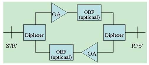
Figure 1 Optical amplifier solution 
Figure 2 Repeater (OEO) solution
The above is based on the discussion of the PMD using the standard 1000BASE-PX20. Non-standard PMD can also be used to increase the optical power of the EPON system by increasing the transmit optical power of the OLT / ONU and / or increasing the receiving sensitivity of the OLT / ONU Power budget. The disadvantage of using this method is that the industry-standard optical modules cannot be used, and the customization cost is relatively high. If the cost is not very sensitive to the application field or the cost of using the optical amplifier / repeater is higher, the customized optical module method can be used.
2. Topological form of EPON
The EPON application topology generally has two types of tree topology (Figure 3) and bus type (Figure 4). Among them, the tree topology generally adopts an even splitter, while the bus topology generally adopts a non-even splitter. Table 1 and Table 2 list the insertion loss reference values ​​of the two types of splitters, respectively, to facilitate the calculation of power consumption. 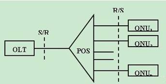
Figure 3 Tree topology 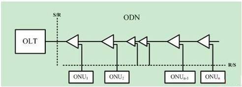
Figure 4 Bus-type topology
Table 1 Typical insertion attenuation reference value of splitter 
Table 2 Insertion attenuation reference value of non-uniform beam splitter 
The topological form has a greater impact on the transmission distance of EPON, mainly the power budget. In order to achieve a longer transmission distance, a smaller branch ratio is generally selected for the tree topology, and a longer transmission can be transmitted. It can transmit (23.5-10.7) /0.3≈42.5km in the case of 1: 8 equalization (not considering other factors such as device and fiber aging), and can transmit in the case of 1: 4 equalization (23.5-7.3) // 0.3≈54km (same as above), in the extreme case where there is only one ONU without splitter directly, it can transmit 23.5 / 0.3≈78.3km (same as above). For the bus topology, in order to achieve a longer transmission distance, in addition to controlling the number of splitter stages, it is necessary to pay attention to control the splitting ratio of the splitter. However, for the application of this topology, the location of each ONU site is fixed, and the maneuverability is not large, so it is mainly necessary to consider from the aspect of how to amplify the optical power. See the discussion in Section 1 for details.
3. EPON dispersion
In the EPON system, 1310nm wavelength is used for upstream, and 1490nm wavelength is used for downstream. The optical fiber ITU-T G.652 fiber is used. We know that the zero dispersion wavelength of G.652 fiber is in the range of 1300 ~ 1324nm, and the upstream wavelength is exactly in this range, so FP lasers can be used for the requirements of ONU spectral characteristics are not high. For the downstream 1490nm not in the zero dispersion wavelength range, for long-distance EPON systems, the OLT must use a DFB laser with a narrow spectral width to reduce the dispersion cost.
4. EPON timing requirements
There are three times in the EPON protocol. One is the maximum RTT of the system (Figure 5), one is the registration window opening time, and the other is the DBA polling cycle. When the transmission distance is extended, the RTT of the ONU furthest from the OLT has the largest RTT. Assuming the furthest ONU is 70km, the RTT is 2 × (70000/2 * 108) = 700us (the speed of the optical signal in vacuum is 3 × 10⁸m / s, the speed in the optical fiber is calculated according to 2 × 10⁸), so in this case, the registration window time of the EPON system should be at least 700us. From the above analysis, it can be seen that as the transmission distance increases, the registration time will inevitably increase. Another consideration is the DBA polling cycle. From Figure 6, it can be seen that the DBA polling cycle should be at least greater than the system's maximum RTT (that is, the farthest ONU round-trip time). It can be seen that the DBA's efficiency is longer in the case of long distance Low, in most cases, it is recommended to use SBA (Static Bandwidth Allocation) algorithm instead of SBA. 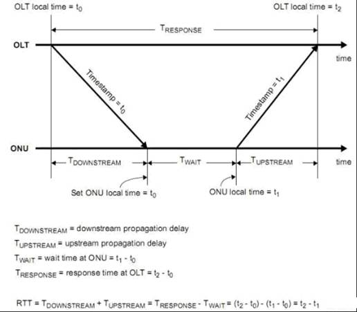
Figure 5 RTT (round trip time) diagram 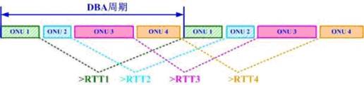
Figure 6 Schematic diagram of DBA polling cycle
5. Conclusion
Considering the above factors, we have verified on the EPON system of Wuhan Changguang Technology Co., Ltd. Practice has proved that by adjusting the maximum polling period without adjusting the physical layer parameters, it is possible to transmit 60km at a 1: 8 equal branch ratio. Through the OEO method, a 1:32 branch ratio of 80km was achieved. At present, the company's related long-distance EPON products have been sold in batches, and the above research has been tested by the market.
references:
[1] IEEE Standard 802.3ah-2004 [S].
About the author: Wang Lixin (1967-), female, master, senior engineer, major research direction in computer communications. Hu Baomin (1977-), male, Ph.D., product director of Wuhan Changguang Technology Co., Ltd. The main research direction is data communication and access network.
Cat6 Cable Diagram,Cat8 Plug,Belgium Mold For Telephone Plug,Phone Sockets Plugs
Dongguan Fangbei Electronic Co.,Ltd , https://www.connectorfb.com