This paper describes the various active noise reduction topologies and analyzes the difficulties encountered by the original designer and contract manufacturer in the production process. Another challenge in the development process is the active noise reduction loop itself. This article will describe the necessary steps to design an active noise reduction feedforward headset based on the AS3415 active noise reduction chip.
Before we officially started making an active noise canceling headset, we needed a special audio device. The first is an audio measurement system for measuring frequency response and phase response. Audio devices are available from Audio Precision, BrüelKjaer, Soundcheck and more. In addition to audio measurement systems, the human ear simulator is also an important part, such as IEC711 (in-ear active noise reduction products) from Head AcousTIcs, BrüelKjaer or GRAS or HeadTorso simulators (headwear and earmuffs). The human ear simulator can be used to simulate human ear response when measuring earphone characteristics. These artificial ears incorporate a highly accurate microphone that measures the sound that people actually hear when they wear headphones. A speaker is also required to measure the passive attenuation characteristics of the headphones as part of the filter design. This speaker should be a two-way speaker, and preferably a coaxial two-way speaker to ensure that the high-frequency and low-frequency transmission distances from the speaker to the earphone are equal. Finally, the AS3415 evaluation board is required, which contains all the necessary connectors and preamplifiers to make the performance testing process as smooth as possible.
Why do you want to test the performance of your headphones?
The acoustic performance of each headset is different. The reason is simple because the headphones use different components, such as speakers with different impedances and transfer coefficients. And the elastic pad of each earphone and the front and rear sound chambers are also different.
To make active noise canceling headphones, it is important to understand the characteristics of the headphones in order to achieve good noise reduction performance. Active noise reduction feedforward headphones use ECM microphones to capture noise outside the headphones. The electronic circuit produces an anti-noise signal that is then played through the speaker. In theory, the ANC loop is a simple inverter circuit, but it is not. Since the different components of the earphone affect the frequency response and phase response, a simple inversion does not allow the ANC to meet performance requirements. In order to understand the performance of the headphones in terms of gain and phase, the performance test of ANC headphones is particularly important.
In order to get the ideal ANC filter curve, we must use the equipment mentioned in the first paragraph to make three measurements. The first measurement is a passive attenuation measurement, as shown in Figure 1.
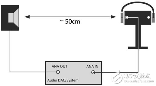
Figure 1: Feedforward performance measurement
We use a coaxial speaker to emit a 20Hz-22kHz swept sound wave and measure the sound waves that reach the human ear. The sound waves reaching the human ear can be measured using a microphone inside the human ear simulator. In this way, we measured the noise attenuation caused by the headphones themselves, that is, passive attenuation.
As shown in Figure 2, the second term is the frequency response measurement of the microphone that captures the noise. Similarly, the sinusoidal sweep signal is played through the coaxial speaker and collected by the ANC microphone.
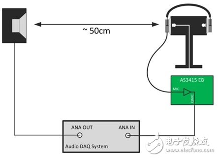
Figure 2: Feedforward Performance Measurement II
The third, and last, (Figure 3) is the frequency response and phase response measurement of the internal speakers of the headset. The 20 Hz to 22 kHz sweep signal is emitted by the speaker inside the earphone, which is collected by the microphone in the artificial head used for the test. This test measures the transfer function of the noise reduction signal as it is broadcast through the speaker and how the signal is received by the human ear. Phase is important for all three measurements. If the anti-noise signal broadcast by the speaker has the same phase as the noise entering the human ear from the environment, the noise will not be attenuated and will be amplified.
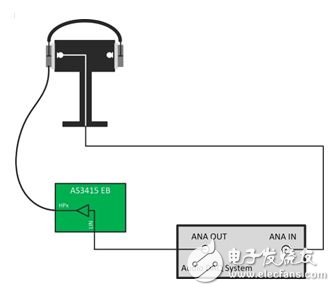
Figure 3: Feedforward Performance Measurement III
Calculate the ideal value of the active noise reduction filter
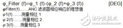
Once these three measurements are completed, we can use the measurements to calculate the ideal value of the ANC filter. The required filter amplitude is calculated as follows:
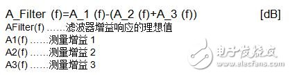
The phase of the required filter is calculated as follows:
The calculation results can be easily obtained from an Excel spreadsheet. A filter example is shown in Figure 6. The example frequency response and phase response indicate that it is difficult to make an ideal noise reduction signal using only one full-bandwidth inverting amplifier.
Development filter
The key to a good ANC headset is the design of the filter. If the filter design is not reasonable, even the best ANC chip is useless. The goal of the filter design is to match the gain and phase response as much as possible. The better the match at a particular frequency, the better the ANC performance. Because it is analog signal processing, the simulation of the filter is usually done by the spice simulation tool. Figure 4 is a spice simulation circuit that embodies the signal path of the ANC microphone filter.
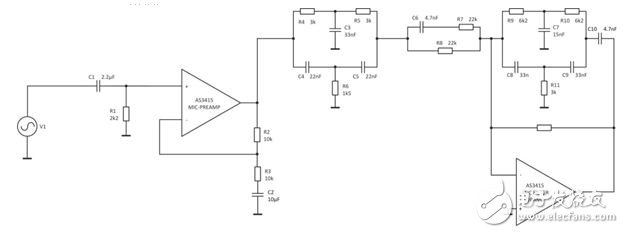
Figure 4: Spice Filter Simulation Example
The purpose of the ANC filter design engineer is to match the gain and phase response in the Figure 4 filter simulation line to the calculated ideal curve. Typical filters used today are one-stage low-pass filters, notch filters, overhead and low-profile filters. Designers must understand the different topologies and calculation methods for cutoff frequency, passband, and stopband. This is certainly not a simple task, especially when they are not used to using the spice simulation tool and the analog filter development tool.
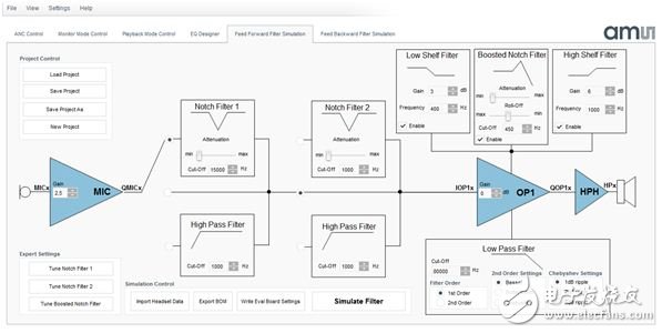
Figure 5: AS3415 Feedforward Filtering Simulation Tool
To solve this problem, the AS3415 evaluation software integrates the feedforward filter simulation tool, as shown in Figure 5. Design engineers can use this tool to design an ideal ANC filter. This tool provides a pre-defined filter architecture that replaces the practice of modifying part values ​​and filter structures. Based on the filter structure simulated for many different customers, these predefined filter structures can cover 90% of ANC acoustic requirements. Figure 6 shows the simulation results for the tool. The green curve represents the ideal ANC gain and phase response, and the blue curve shows the simulation results of the ANC filter fabricated using the tool of Figure 5. When designing filters, it's important to know which bands we want to focus on. The ANC headset operates with a specific frequency range, not due to the limitations of the AS3415 itself, but to the speed of sound propagation and the acoustic characteristics of the headphones. If we only focus on the gain response in an ideal filter curve, it is easy to design a filter that fits this curve. But the problem is that the phase must be matched at the same time in the design of the ANC filter. Since the phase at higher frequencies is rotated by almost 180 degrees, the designed filter is likely to match the frequency response and not the phase. Depending on the headphones and their phase response, we can usually match filters below 1.5 kHz. The higher frequency part needs to be as attenuated as possible. If these unmatched high frequency parts are not attenuated, noise may be introduced. We attenuate the noise at low frequencies, but if the phase of the high frequency is mismatched, the noise is amplified. In order to avoid this phenomenon, we will try to reduce the gain in areas that cannot be matched. The green transparent area in Figure 6 represents the minimum mismatch in gain and phase that we typically achieve. The red area is the part we want to decay as much as possible. A good balance must be achieved between high frequency attenuation and phase response. If it is attenuated too much at high frequencies, it will affect the phase response of the low frequency, which may lose the effect of ANC.
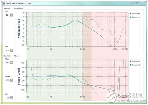
Figure 6: Simulation results
Filter inspection and ANC testing
After obtaining a satisfactory filter curve, the AS3415 filter simulation tool also provides a bill of materials output function. Since the tool matches the evaluation board of the AS3415, the items listed in the bill of materials can be soldered to the evaluation board to test the performance of the ANC with the filter. The test consists of two parts: one is the passive attenuation test when the earphone is worn on the artificial head, and the other is the frequency response test when the AS3415 chip is turned on and the feedforward noise reduction function is configured. The ANC performance is calculated as follows:
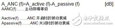
These calculations can be done in an Excel spreadsheet and generate an ANC noise reduction performance graph in the audio range. This ANC noise reduction performance graph is very important and common in the design and production of noise canceling headphones. Development tools and application notes and templates for AS3415 development tools and ANC noise canceling headphones are now available.
The 1U Brush Cable Management Panel mounts to a standard 19" rack to organize cables while keeping dust and dirt out of the rack. Constructed of high-quality steel with high-density nylon bristles, the 1U brush plate creates a clean looking point of entry and offers cable separation for simple cable organization. The brush panel also promotes proper airflow through the rack by closing off open spaces between equipment, this cable organizer comes complete with 2 sets of rack screws for easy installation.
Brush Type Cable Management,Brush Cable Management,1u brush panel,1U Cable Management
NINGBO UONICORE ELECTRONICS CO., LTD , https://www.uonicore.com