The use of batteries in everyday devices is becoming more and more popular. In many of these products, charging connectors are difficult or unusable. For example, some products require a sealed enclosure for sensitive environmentally sensitive electronic components and allow for convenient cleaning or disinfection. Other products may be too small to accommodate connectors, and if battery-powered applications include moving or rotating parts, there is no longer a need to consider wired charging in products of this type. In this and other applications, wireless charging is useful for increased reliability and robustness.
There are many ways to wirelessly transfer power. Capacitance or inductive coupling is common over short distances of less than a few inches. Discussed in this article is a solution using inductive coupling.
In a typical inductively coupled wireless power transfer system, the AC magnetic field is generated by a transmitting coil, which in turn causes an AC current in the receiving coil, just like a typical transformer system. The main difference between a transformer system and a wireless power transfer system is that in a wireless power transfer system, the gap is isolated by an air gap or other non-magnetic material to isolate the transmitter and receiver. Furthermore, the coupling between the transmitting coil and the receiving coil is typically very weak. Coupling of 0.95 to 1 is common in transformer systems, but in wireless power transfer systems, the coupling factor is between 0.8 and as low as 0.05.
The basic principle of wireless chargingThe wireless power transfer system consists of two parts separated by an air gap: a transmit (Tx) circuit that includes a transmit coil, and a receive (Rx) circuit that includes a receive coil.
When designing a wireless power transfer battery charging system, the primary parameter is the amount of power that actually adds energy to the battery. This received power depends on many factors, including:
* the size of the transmission power;
* The distance and alignment between the transmitting coil and the receiving coil are often expressed by the coupling factor between the two coils;
* The tolerance of the sending and receiving components.
The primary goal of any wireless power transmitter design is that the transmit circuitry is capable of generating a powerful magnetic field to ensure the required received power is provided under the worst power transfer conditions. However, it is also important to avoid overheating of the receiver and excessive electrical stress in the best case. This is especially important when the output power requirements are low and the coupling is strong. An example is a battery charger when the battery is fully charged and the Rx coil is placed close to the Tx coil.
Simple but complete transmitter solution with the LTC4125
The Transmitter IC is designed for use with a variety of different battery charger ICs in the Linear Technology product library. This companion device acts as a receiver, such as the LTC4120, which is a wireless power receiver and battery charger IC.

Figure 1: In a wireless power system with a LTC4120-4.2 as a 400mA single-cell Li-Ion battery charger on the receiver, the LTC4125 drives a 24μH transmit coil at 103kHz with a 1.3A input current threshold, a 119kHz frequency limit and 41.5 ° C transmission coil surface temperature limit.
The LTC4125 provides all the features needed for a simple, powerful and secure wireless power transmitter circuit. In particular, the device is capable of regulating output power in accordance with receiver load requirements and detecting the presence of conductive foreign matter.
As mentioned earlier, the transmitter in the wireless charger system needs to generate a powerful magnetic field to ensure that the required received power is provided under the worst power transfer conditions. To achieve this goal, the LTC4125 uses Linear Technology's proprietary AutoResonant technology.

Figure 2: LTC4125 AutoResonant Drive Circuit
The LTC4125 AutoResonant driver circuit ensures that the voltage at each SW pin is always in phase with the current entering this pin. See Figure 2: When current flows from SW1 to SW2, switches A and C are turned on, switches D and B are turned off, and vice versa. Using this method to lock the drive frequency cycle by cycle ensures that the LTC4125 always drives the external LC network at the resonant frequency. This is always guaranteed even when the variables affecting the resonant frequency of the LC resonant circuit are continuously changed, such as the temperature and the reflected impedance of the nearby receiver.
Using this technique, the LTC4125 continuously adjusts the drive frequency of the integrated full-bridge switching circuit to match the actual resonant frequency of the series LC network. In this way, the LTC4125 can efficiently generate a very large AC current in the transmitter coil without the need for a high DC input voltage or a highly accurate LC value.
The LTC4125 also adjusts the pulse width of the series LC network waveform by changing the duty cycle of the full-bridge switching circuit. By increasing the duty cycle, the series LC network produces more current, thus providing more power to the receiver load.
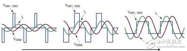
Figure 3: LTC4125 Pulse Width Scan – As the duty cycle increases, the voltage and current in the Tx coil increase.
The LTC4125 periodically scans the duty cycle to find the optimum operating point for the receiver load condition. This optimal power point search allows for large misalignment between the air gap and the coil under all operating conditions while avoiding overheating of the receiver circuit and excessive electrical stress. The scan cycle is easily set with a single external capacitor.
The system shown in Figure 1 is capable of allowing considerable coil misalignment. When the coil is misaligned, the LTC4125 is able to adjust the strength of the generated magnetic field to ensure that the LTC4120 receives the full charge current. In the system of Figure 1, up to 2 W of power can be transmitted over distances of up to 12 mm.
Conductive foreign object detectionAnother essential feature of any feasible wireless power transfer circuit is the ability to detect the presence of conductive foreign matter in the magnetic field generated by the transmitting coil. Transmitters used to provide more than a few hundred milliwatts of power to the receiver must be able to detect the presence of conductive foreign matter to prevent eddy currents from forming in foreign matter, causing undesirable temperature rises.
The LTC4125's AutoResonant architecture allows the IC to detect the presence of conductive foreign matter in a unique way. Conductive foreign matter can reduce the effective inductance value in a series LC network. This causes the AutoResonant driver to increase the drive frequency of the integrated full bridge circuit.
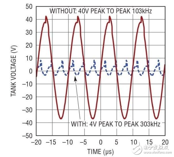
Figure 4: Frequency comparison of the LTC4125 transmitter LC resonant circuit voltage with and without conductive foreign matter.
The graph shown in Figure 4 compares the frequency of the voltage generated by the transmitting coil with and without conductive foreign matter.
The LTC4125 sets the frequency limit through a resistor divider that reduces the drive pulse width to zero during the AutoResonant drive beyond this frequency limit. When the LTC4125 detects the presence of a conductive foreign matter, the transmission power is stopped in this manner.
Note that by using this frequency shift phenomenon to detect the presence of conductive foreign matter, a trade-off can be made directly between the detection sensitivity and the component tolerance of the resonant capacitor (C) and the transmit coil inductance (L). For a typical initial tolerance of 5% for each L and C value, this frequency limit can be set to 10% higher than the natural frequency formed by the expected typical LC value for reasonable sensitivity of foreign object detection and reliable transmission. Circuit design. However, a tighter 1% tolerance component can also be used, while the frequency limit is set to only 3% higher than the expected typical natural frequency to achieve higher detection sensitivity while still maintaining the design's robust robustness.
Power variation flexibility and performanceBy simply changing the values ​​of the resistors and capacitors, the same application circuit can be paired with different receiver ICs to achieve higher wattage charging.

Figure 5: In this wireless power transfer system, the LTC4125 drives a 24μH transmit coil at 103kHz with a frequency limit of 119kHz, the transmit coil surface temperature is limited to 41.5°C, and at the receiver end, the LT3652HV acts as a 1A single-cell LiFePO4 (3.6V floating) Voltage) Battery charger used.
Thanks to the high efficiency full-bridge driver on the transmit circuitry, the receiver circuit uses a high efficiency step-down switching topology, enabling up to 70% overall system efficiency. This overall system efficiency is calculated using the battery output of the DC input and receive circuits of the transmit circuit. Note that the quality factors of the two coils and their coupling are equally important to the overall efficiency of the system and to the rest of the circuit.
All of these features of the LTC4125 can be implemented without any direct communication between the transmitter and receiver coils. In this way, a simple application design can be implemented, covering various power requirements up to 5W and many different actual coil arrangements.
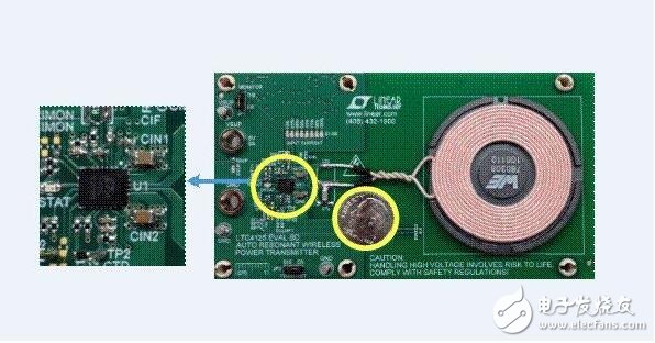
Figure 6: Typical and complete wireless power transmitter board using the LTC4125.
Figure 6 shows that the overall size of a typical LTC4125 application circuit is small and simple. As mentioned earlier, most of the functions can be customized with external resistors or capacitors.
in conclusionThe LTC4125 is a powerful new IC that provides all the features needed to make a secure, simple and efficient wireless power transmitter. AutoResonant technology, optimal power search, and frequency-based conductive foreign object detection alleviate the design burden of a full-featured wireless power transmitter with superior distance and misalignment tolerance. The LTC4125 is an easy and extraordinary choice for a reliable wireless power transmitter design.
Shenzhen Kaixuanye Technology Co., Ltd. , https://www.iconlinekxys.com