Let's take a first look at the relay drive circuit.
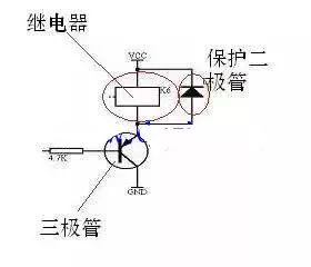
This is a classic relay drive circuit diagram that you can easily find online or in most standard electronics textbooks. It’s a fundamental building block for connecting microcontrollers to high-power devices.
But why should we understand this diagram?
Well, microcontrollers are low-power devices, usually operating at 5V or lower with current levels in the milliamp range. This makes them unsuitable for directly controlling high-power components like motors, solenoids, or contactors. That’s where a power driver comes in — and a relay is one of the simplest and most common examples.
So what exactly does "relay drive" mean? On one hand, it refers to driving the relay itself, since a relay is essentially a high-power load for the microcontroller. On the other hand, relays can also be used to control even more powerful devices, such as intermediate relays or contactors. In short, a relay acts as an interface between the microcontroller and these high-power loads.
Many beginners wonder: How can a small chip control something as strong as a motor? The answer lies in the use of components like transistors and relays, which act as intermediaries to amplify the signal and handle the higher current required.
Now, how do we understand this circuit?
It’s actually not too complicated if you break it down step by step. Let’s go through it together.
First, let’s focus on the transistor. Transistors are one of the most essential components in electronic circuits. They have two main functions: amplification and switching. For this particular circuit, we’re interested in the switching function.
Think of the transistor as a switch. Imagine a water faucet — when you open it, water flows; when you close it, the flow stops. Similarly, the transistor controls the flow of current to the relay coil.
In this analogy, Vcc is like the water source, the relay coil is like the turbine, and GND is the drain. The base of the transistor (connected to the MCU) is like the handle of the faucet. When the MCU sends a low signal, it opens the “faucet,†allowing current to flow through the relay coil and activating it. When the signal is high, the “faucet†closes, and the relay turns off.
That’s the basic idea of how a transistor works as a switch in this circuit.
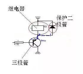
Another important component in the diagram is the protection diode. While it might seem confusing at first, it plays a critical role in protecting the transistor from voltage spikes that occur when the relay coil is turned off. These spikes can damage the transistor if left unchecked.
Even if you don’t dive deep into the theory, it’s important to remember that this diode is almost always present in relay circuits. And here’s a key tip: the cathode of the diode must be connected to the positive supply (Vcc), while the anode is connected to the relay coil.
Five And More Digits LED Display
Five And More Digits Led Display,Led Display Red Color,10 Segment Led Display,Yellow Segment Led Display
Wuxi Ark Technology Electronic Co.,Ltd. , https://www.arkledcn.com