Let's take a first look at the relay drive circuit.
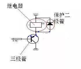
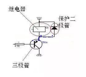
This is a standard diagram of a relay drive circuit. You can easily find similar images online or in textbooks. It's a common example used to explain how microcontrollers interface with high-power devices.
But why is it important to understand this diagram?
Microcontrollers are low-power devices, typically operating at 5V or lower, and their output current is usually just a few milliamps. This makes them unsuitable for directly controlling high-power components like motors, solenoids, or contactors. That’s where a power driver comes into play—specifically, a relay drive circuit.
A relay drive serves two main purposes. First, it allows the MCU to control the relay itself, which acts as a power device. Second, the relay can be used to drive other high-current loads, such as larger relays or contactors. In short, the relay acts as a bridge between the low-power microcontroller and high-power systems.
It's fascinating to think about how a tiny chip can control something as powerful as an electric motor. Many beginners wonder how that works. The answer lies in the use of components like transistors and relays, which act as intermediaries to amplify the signal and provide sufficient current.
So, how do we interpret this circuit?
Understanding the circuit isn’t too difficult if you break it down step by step. Let me guide you through it:
The key component here is the transistor. Transistors are fundamental in electronics and have two main functions: amplification and switching. For this circuit, we focus on the switching function.
Think of the transistor as a switch. Imagine a faucet, where the water pressure represents the voltage, and the flow of water is the current. The MCU controls the "handle" of the faucet through a resistor.
When the MCU outputs a low voltage, it turns the transistor on, allowing current to flow through the relay coil. This activates the relay, causing its contacts to close. When the MCU outputs a high voltage, the transistor turns off, cutting off the current and deactivating the relay.
This is the basic switching behavior of a transistor. In simple terms, you can think of it as an electronic switch controlled by voltage rather than a physical button.
Another important part of the circuit is the protection diode. It might seem confusing at first, but it plays a critical role in protecting the transistor from voltage spikes caused by the relay’s coil when it turns off. Even if you don't need to dive deep into the theory, it's essential to remember that this diode is almost always present in such circuits. Also, pay attention to its orientation: the cathode should be connected to the positive supply (Vcc), while the anode connects to the relay coil.
By understanding these basics, you’ll gain a solid foundation in how microcontrollers interact with real-world components. This knowledge is crucial for anyone working with embedded systems or automation projects.
Wuxi Ark Technology Electronic Co.,Ltd. , https://www.arkledcn.com